Cleanliness and Drainability are among the most critical issues biopharmaceutical manufacturers or owner companies must confront with their process lines. Plants making active pharmaceutical ingredients (API) or ingredients used in the manufacture of pharmaceuticals are increasingly being held to the same sanitary standards as biopharmaceutical manufacturers. Therefore, optimizing fluid system components used in these systems must take both cleanliness and drainability into consideration.
Some manufacturers run one operation continuously. More often than not, manufacturers run multiple batches and must clean between them using SIP (steam-in-place); CIP (clean-in-place), which uses a chemical agent in the cleaning process; or both. In a properly constructed system, when a valve is shut off, the entire system downstream should drain completely, thereby minimizing residual puddles, reservoirs or entrapment along process lines or in and around valves or fittings.
Variables that will impact a system’s drainability and cleanability include: system slope; deadlegs; interior surface finish of tubing; valve and fitting selection and design; and fitting-to-valve ratio. Owners and contractors alike can take steps in the design and construction phase to enhance the cleanability and drainability of a system. However, the onus rests on the owner to make it known that drainability and cleanability are top-line requirements.
System Slope, Deadlegs and Interior Surface Finish
Some specific guidelines concerning system slope and drainability are given in AS ME-BPE (the American Society of Mechanical Engineers’ BioProcessing Equipment Standard, www.asme.org/Communities/ Technical/BPE/) section SD 3.12. Although this standard does not designate a specific slope, most companies use the guideline of a minimum ⅛ inch or ¼ inch per foot. In other words, for every foot of tubing, the line should drop a minimum of ⅛ inch to ¼ inch.
Deadlegs are sections of tubing (typically tees leading to valves or valve assemblies), characterized by a discontinuity of flow. When cleaning in place, chemicals or steam may not reach these locations, or fluid may be held up there and not fully drain, leading to contamination. Minimizing the number of deadlegs when designing a system is vital. Deadlegs can be managed in three ways, listed below in order from least to most desirable.
In Configuration A, a tee fitting with three welds creates a horizontal line to a valve. The deadleg is the area between the tee fitting and the valve. Of the three options, this one creates the longest deadleg because the valve’s proximity to the intersection is limited by the tee stub. With this configuration, the best solution is to choose tees whose stubs are shortest in length and widest in diameter. This type of setup will facilitate access when cleaning and will minimize the area for fluid hold-up.
In Configuration B, a valve is used instead of a tee fitting. The tee is created by boring a hole into the side or bottom of the valve, then welding a vertical line into the valve. The distance to the valve on the vertical line (the deadleg) is shorter than in Configuration A because the welded tee fitting is not part of the flow path.
In Configuration C, the best design solution, the deadleg is eliminated altogether through the use of a custom valve assembly. In these assemblies, two valves actuate from the same block, one controlling vertical flow and the other horizontal flow. Owners and designers should look into block body-package options, as these assemblies are often more cost-efficient than two separate valves.
The interior surface finish of tubing affects both drainability and cleanability. A smooth finish, with no porosity or pitting, provides better performance in both areas. Cleanability can be enhanced further by applying an electropolish, which adds a chemically inert layer to inhibit corrosion. Special tools may be used to measure interior surface finish, along with a visual examination.
Selection and Design
Careful consideration is needed for valve selection. One valve is not just as good as another. In critical shut-off applications, the two most common types of valves are the weir-style and the radial diaphragm. The weir-style valve is the industry standard, with a track record of solid performance in validated systems. However, the weir-style sealing design has potential for entrapment or contamination. The diaphragm is designed to seal on a bead outside the weir area. In the open position, though, the diaphragm lifts up and flexes, exposing the valve body along the perimeter of the bowl. As the valve closes, the diaphragm closes back toward the body of the valve, allowing small quantities of fluid to become trapped.
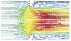
Figure 1. Computational Fluid Dynamics (CFD) show the effect of gasket
extrusion into the flow path of the ISO 2852 fitting.
Newer radial diaphragm valve designs correct this imperfection. In these designs, the diaphragm seals along the edge of the valve’s bowl. At no time does the diaphragm lift beyond the edge of the bowl. As a result, entrapment does not occur. Further, the bowl shape, inlet, and outlets are configured to ensure that the flow path is cleanly swept and optimized for full drainability.
In choosing between the weir-style valve and a radial diaphragm valve, owners should carefully consider the sensitivity of the application as to drainability, entrapment, contamination potential and system flow requirements. For example, the equivalent-size weirstyle valve would provide a higher flow rate and be the appropriate choice for applications requiring a higher flow, while radial diaphragm valves are well suited for applications where cleanliness or high cycling is critical.
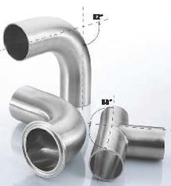
Fittings are another important factor in drainability. Special angled elbow fittings (relatively new to the marketplace) are targeted to 88 degrees or 92 degrees, with a tight tolerance of +/- 0.5 degrees (Figure 2, p. 46). Such angles ensure proper drainability. With standard 90-degree-angle fittings, AS ME-BPE permits a typical variability of +/- 1.3 degrees. Some contractors will try to use this tolerance and presort standard 90-degree fittings into those in the acute direction and those in the obtuse direction for use in different slope applications. This process is time-consuming and inexact.
Usually, standard 90-degree fittings require some additional angling to obtain the desired slope. This is accomplished through two common methods. One method requires a facing tool. A mitered cut is made near the end of the 90-degree elbow. A straight piece of tubing is then butt-welded to the mitered cut, creating a slope. Some bending may be required to adjust the slope.
A second method requires only one’s bare hands. A straight piece of tubing is butt-welded or otherwise attached to the fitting. Then, the installer grips the straight piece of tubing and forces it to the desired slope or position. One section is mitered, and the other is bent into place.
Neither of these methods is very accurate. In fact, some biopharmaceutical manufacturers prohibit these methods. When forcing tubing to a desired slope or position, one runs the risk of compromising the integrity of the internal surface finish and inviting contamination. In addition, tubing can spring back from its forced position with a change in temperature or when uncoupled for maintenance, upsetting the intended angle and resulting in reassembly challenges.
The alternative to these manual methods is angled fittings bent to 88 degrees or 92 degrees. These angled fittings are typically manufactured in an elbow or tee configuration, faced for butt welding and fitted with welded flanges for clamp-end fittings or with threads for threaded fittings.
Figure 2. Special angled elbow fittings at 88 degrees and 92 degrees
ensure proper drainability.
Conventional tri-clamp fittings are common. However, the four-bolt ANSI flange, a piping standard, is unsanitary and therefore inappropriate for biopharmaceutical manufacturing and other sanitary systems. If the conventional IS O 2852-type tri-clamp fitting is to be employed in a biopharma manufacturing system, the owner should be aware of its potential issues regarding drainability and flow obstruction. As the clamp in an IS O 2852-type fitting tightens, the gasket will extrude into the interior flow path. With thermal cycling, the bore intrusion may increase. Computational Fluid Dynamics (CFD) demonstrates that such intrusion causes turbulence in the flow path and a potential hold-up when the system is drained (see Figure 1).
Alternatively designed fittings prevent gasket extrusion into the flow path. They are manufactured to prevent over-tightening and provide an alternative space into which the gasket may extrude (during pull-up and clamping) or expand (during thermal cycling).
Fitting-to-Valve Ratio
Although no accepted ratio of fittings to valves is in practice, the dictum “less is more” should be used as a guide. In choosing valve designs, owners and designers should aim to reduce the number of fittings and valve bodies, as a means of improving overall system efficiency, cost and performance.
Quality valves are available with multiple combinations of inlets and outlets, so one multi-valve may do a job that used to require two or more individual valves. Such designs not only reduce the number of valve bodies, but also the number of fittings, since at least two fittings (or welds) are required for each valve. In other words, smart valve choices result in a reduction in valves, a higher fitting-to-valve ratio, and, likely, a reduction in overall system size and deadlegs.
One of the more critical valve applications occurs at point-of-use outlets. Traditionally, these valves appear as a zero-static tee. While the vertical stem of the tee may drain well, the horizontal sections may not. In some cases, 90-degree elbows may be added to (or replaced) on each side of the horizontal tee sections, creating an elbow header.
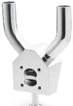
Figure 3. The Viking arrangement ensures full
drainability. It is an alternative to a point-of-use
valve with a static tee.
A better option is the “Viking” design, in which the two horizontal pieces of the tee formation are no longer horizontal at all (Figure 3). Rather, they are configured vertically and bend 45 degrees before entering the valve. Gravity does all the work to ensure complete drainability. In addition, the distance between the two vertical drops in a Viking formation coincides with AS ME-BPE recommended dimensions for “U” drops. Weir-style or radial diaphragm valves may be employed in Viking formations.
Other Considerations
Many subtleties come into play when designing systems. The following are key factors:
- Properly sized tubing is paramount. Proper inside diameter of the tubing is relative to the volume of the system and the pressure of the cleaner to be used. The cleaner on hand must provide sufficient force to clean out the tubing.
- Steam-in-place is an effective cleaning method, but systems must be designed to tolerate it. Some elastomers (in gaskets or valve diaphragms) and cast-body products (in pumps, for instance) are not optimal for steam. In selecting gaskets and diaphragms, customers should always specify steam-grade. Black residue in the system is a sign of a low-grade elastomer that has eroded during steam cleaning. As for the steel in pumps, valves and the like, it must be forged, wrought or machined. The problem with casting is that controlling the metallurgy is difficult. The process can give off ferrite ions that cause rust to develop in the system when they come in contact with steam. Teflon can also be used in systems that will be steam-cleaned.
- Welds must be high-quality. Serious problems can occur when welding two pieces of stainless steel with dissimilar metallurgy. For example, the weld pool can become asymmetric, favoring the low sulfur side, and the root of the weld may shift away from the joint. This can be minimized by matching sulfur contents within +/- 0.010 percentage points. Greater differences than that require adjustments to weld setup to achieve full penetration to the root of the joint.
- The system must be properly supported. Sagging occurs from the weight of the tubing, as well as from technicians stepping on it or using it as a handrail. To eliminate sagging, a sloped system requires support in the form of sloped tubing hangers, made specifically for such a system.
Owners, designers and contractors must make careful, informed decisions concerning fluid system components if they are to avoid significant monetary losses or validation failures because of contamination or poor drainability. Valves, fittings and system slope are all critical to the proper functioning of the larger system.
As the industry moves forward, improved fluid system components will be integrated into biopharmaceutical manufacturing systems. Components with innovative designs that reduce the margin for error, such as special angled elbow and tee fittings, the latest generation fittings that prevent gasket extrusion into the flow path, multivalves and Viking point-of-use valves will replace less precise alternatives and enhance system cleanability and drainability.
About the Author
Michael Bridge is a market manager for Swagelok Biopharm Services Co., a strategic business unit of Swagelok Co. Based in Amherst, N.Y., this business unit develops and manufactures fluid system component technologies for the biopharmaceutical and other sanitary industries worldwide. For more information, visit www.swagelok.com.


