Recently, Quality Risk Management (QRM) has become a mandatory regulatory requirement for drug manufacturers. The U.S. Food and Drug Administration (FDA) and the European Medicines Agency (EMA) publish guidelines and requirements which customers and vendors are expected to follow. Guidelines such as “Process Validation: General Principles and Practices” by the FDA and Annex 15 issued by the EMA offer input to help drug manufacturers design processes correctly.
Based on the new process validation model published by the FDA (Figure 1), validation is never finished, but is instead a process of continuous improvement. Maintenance and calibration activities of instruments are part of stage three in the model.
Figure 1: The FDA Process Validation Model.
QRM is an overall and continuous process to minimize product quality risk. Instrument calibration/verification interval definitions are part of QRM risk analysis, and guidelines for these procedures are described by the FDA and EMA accordingly. Selecting the correct instrument for the application is absolutely crucial in the design phase of the project, and the criticality of the measuring point defines the required reliability and measuring accuracy of the instrument.ISO 9001:2008 section 7.6 requires instruments to be calibrated or verified at regular intervals. The following basic requirements have to be fulfilled:
• Calibration/verification must be traceable to a national standard
• Calibration/verification must be performed at regular intervals, and
• Calibration/verification must be documented
CALIBRATION AND VERIFICATION
The first step in verification is to determine if the instrument is still operating within specifications before it is taken out of service for calibration. A calibration of an instrument — for example, a flowmeter — involves determining and documenting the difference between the measured and the correct value.
Traceability is accomplished by a formal comparison to a standard which is directly or indirectly related to national standards. Detected deviations between the measured value and the reference value can be corrected after the calibration by adjusting the calibration factor. A calibration protocol is issued to document the findings, and recorded for possible audits.
A substantial number of FDA warning letters are issued because remedial action after a calibration check has been considered insufficient.
Documentation about instruments and their maintenance activities has to be filed for inspector visits. Even if a flowmeter theoretically could be operated for 25 years without calibration due to its excellent safety and reliability parameters, it would most likely trigger some critical questions during an audit if no paperwork was available to prove it remained within calibration.
Calibrations are expensive, but provide very clear results for the user. Even though many instruments have proven exceptionally long-term stability which exceeds the entire lifetime of the equipment, they still have to be checked regularly to avoid legal implications.
Today, modern instruments have built-in technology to simplify compliance and verification. Several instrument vendors offer this capability, but all approach the solution in different ways.
AUTOMATIC VERIFICATION
Automatic verification is an accepted procedure. For example, Heartbeat Technology from Endress+Hauser has been tested and independently certified by the European agency TÜV. Heartbeat verification fulfills all requirements specified in ISO 9001:2008 section 7.6 and can be used interchangeably with traditional wet calibrations for traceable instrument checks.
Heartbeat Technology continuously monitors the entire signal chain for deviations within a very tight band. The failure threshold is defined by the specified accuracy of the instrument. Therefore, Heartbeat Diagnostics will trigger an alarm as soon as the sensor or instrument is no longer operating within the original specification. With automatic verification, a sensor does not have to be removed from the process until the diagnostics sound an alarm.
The entire signal chain of the instrument is analyzed for possible errors and their subsequent impact on the system and its measuring accuracy. Typically, a failure modes, effects, and diagnostic analysis (FMEDA) is used during the device design phase to identify critical components in the signal chain.
FMEDA is a systematic analysis technique to obtain failure rates, failure modes and diagnostic capability. The FMEDA technique considers:
• The functionality of each component
• The failure modes of each component
• The effect of each component failure mode on the product functionality
• The ability of any automatic diagnostics to detect the failure
• The design strength (de-rating, safety factors)
• The operational profile (environmental stress factors)
As a result, a proper safety measure has to be assigned to every critical path or component. Measures include digital signal processing and continuous loop checks with the help of internal reference components. In order for an internal component to be used as a diagnostic reference, it has to fulfill special requirements such as factory traceability and exceptional long-term stability.
FLOWMETER VERIFICATION
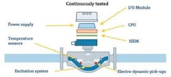
Figure 2: Modern instruments, such as this Coriolis flowmeter, can automatically verify correct operation. Any deviations will send an alarm.
Modern flowmeters, which operate based on a Coriolis, electromagnetic, ultrasonic, vortex or thermal measuring principle, do not have any moving parts that are subject to wear. They have been tried and tested in thousands of applications and are well known for guaranteeing highly stable measurement results over a long period of time.The reason for this long-term stability stems from the technologies’ resistance to wear provided by the lack of moving parts in the sensor. Therefore, for these measuring principles, it is assumed that they will exhibit long-term stability if they are properly selected, sized and installed. Good engineering practice eliminates the possibility of systematic errors.
Verification does not require fluid going through the meter (Figure 2); instead, it verifies a number of internal components (secondary variables), which are closely correlated to the flow measurement.
During verification, the current conditions of the secondary parameters are compared with their reference values, thereby determining the device status. Verification produces a pass or a fail statement, depending on whether the assessment is positive or negative. A traceable and redundant reference, contained in the verification system of the device, is used to ensure the reliability of the results. In the case of a Coriolis flowmeter, this is an oscillator, which provides a second, independent reference frequency.
Coriolis, vortex and ultrasonic flowmeters apply time-based principles, measuring the frequency of the sensor oscillation with the help of quartz clocks as digital frequency generators.
Magmeters rely on precision voltage references to measure the voltage induced in the magnetic field of the sensor.
Flowmeters are often used for many years in biopharmaceutical applications. References with long-term stability ensure that deviations due to aging or external influences are extremely improbable. However, if this should occur, it is immediately detected by the integrated continuous monitoring system. This ensures highly reliable operation and, by detecting errors in a timely manner, prevents the device from working outside of the factory specifications. This increases the safety of plant operation and ensures consistent product quality.
LEVEL INSTRUMENT VERIFICATION
Level instruments do not need calibration as flowmeters do. Level instruments can be verified periodically without process interruption, verifying the accuracy compared to when it was installed.
For this reason, verification is vital to ensure proper operation and to provide added confidence to operators. A modern level instrument equipped with verification capabilities and its ability to conduct continuous automatic internal checks and diagnostics allows for added safety and reliability. Some of these internal checks include:
• Reference pulse
• Quartz synchronization
• Clock verification
• Cycle time measurement
• Supply voltage check
• Temperature monitoring
• Check sum in RAM
• Cable breakage
Level instruments are also able to diagnose process problems. For example, a radar level instrument can monitor for buildup in the area around the horn — the area of the coupling signal — and detect material buildup on the antenna by evaluating the quality during installation as a clean horn. A threshold can be set for build up to notify the operator before the unit would lose its echo. The notification can be from the front display and an analog or open collector output.
PAPERWORK FOR AUDITS
In addition to the continuous monitoring functionality running in the background, a traceable verification report about the health status of the sensor and instrument can be generated on demand. This report is produced, without the need of external devices, directly within the instrument. The operator does not have to write any results down on paper, which makes the entire process faster and reduces costs. The quality of the verification results improve, as there will be fewer mistakes due to human error.
Devices with internal verification can store multiple results in the transmitter. In addition to the verification result (pass/fail), the transmitter logs the actual measured values for all tested parameters. This data can be used for tracking trends in the lifecycle of the measuring point. This allows for timely conclusions regarding the measuring point’s state of health and it assists in preventing unexpected failures. Verification data may be transferred to asset management software for archiving and trend analysis.
By comparing the data from multiple consecutive verifications, trends can be detected and systematically tracked during the lifecycle of the measuring point. This allows for timely conclusions regarding the measuring point’s state of health or process-specific influences on the measurement result.
Continual internal diagnostics and internal verification capabilities reduce maintenance expenditures because calibrations on flow instruments are done only when needed, and diagnostics built into the level devices along with the ability to verify periodically identify problems with instruments. It leads to a better overall equipment effectiveness as it results in less process downtime for maintenance and fewer shutdowns from instrument failures.


