A pharmaceutical manufacturer needs to keep space temperatures in a warehouse between 68°F and 78°F to maximize shelf life of their products. The buildings HVAC control system was designed to issue an alert to plant operating personnel whenever temperatures in the space fall outside a +/- 3.5°F limit from setpoint.
Eichleay Engineers Inc. of California designed the air handling system for the warehouse. Though the system could maintain the tight temperature tolerances there was very little margin for safety, especially in the vicinity of the 25 foot ceiling. Eichleay hired Flomerics Inc. consultants to simulate air flow and temperature in the warehouse using Flomerics Flovent software which is specifically designed for simulating heating and cooling of building interiors. The simulation matched physical measurements that showed that the air handling system alone was just able to hold the customers tight temperature requirements.
Eichleay Engineers requested that Flomerics consultants evaluate several design alternatives, which included addition of fans to increase air circulation within the warehouse. Flomerics identified a fan configuration that met the customers requirements for both temperature variation and air velocity. The HVAC system has been in operation for over a year and the temperatures in the warehouse have never been outside the customers specified range, said Michael Simpson, Mechanical Engineer for Eichleay Engineers.
Tough Requirements for Pharmaceutical Warehouse
The building contains 49,200 square feet of warehouse storage space and has a roof height that varies from 25 to 28 feet. In order to maximize the life of the pharmaceuticals stored in the facility the client established a requirement that the temperature throughout the entire interior space be held to 70°F with an allowable variation of only +/- 3.5°F. In addition, the client required that the building be maintained at less than 50% relative humidity. The outside design conditions varied from 95°F at 90% relative humidity in the summer and -20°F at 20% relative humidity in the winter.
We began the project by using standard computer calculations to design an HVAC system that was capable of keeping the temperature in the building at the required level, Simpson said. The system included a 100 ton DX air conditioning system and duct mounted zone reheat coils for tight temperature control. This system could get us to the right average temperature but left us with very little safety margin. The difficulty was increased by the fact that the client wanted the ability to place pallets in any rack location in the building and stack them up to 19 feet high. Our challenge was to ensure that the temperature at any position and any level in the building is within the required tolerances. Not an easy task!
Air Handling System Alone Could Just Meet Specifications
Construction personnel installed the equipment and performed field adjustments that brought the HVAC performance within specification. They bled air from the HHW piping system, replaced faulty HHW valves and adjusted the air handler controls for supply air temperature to match setpoint requirements. They replaced thermostats with less sensitive thermostats, relocated them to higher elevations and modified temperature setpoints. They modified the HVAC automation control system to lower the supply air temperature. This fine tuning substantially reduced the temperature variations but physical measurements still showed variation in the building from 68°F to 74°F.
Simpson now recognized that the building would require additional air handling equipment to narrow the temperature variations within the space. However, the cost of purchasing and installing stratification fans was too substantial to simply put them in and see if they would work, and hand calculations would not be nearly accurate enough because they could not account for the unique geometry of the building and its contents. So Simpson decided to seek the assistance of a consultant to simulate the airflow and heat transfer within the building with computational fluid dynamics (CFD).
We called the two leading software companies in the HVAC CFD industry. We knew that they both offered people with extensive experience in air flow simulation modeling. One of the companies told us that we would have to wait several weeks before they could even take a look at our problem. Flomerics told us they would be there the next day to give us an estimate and get started on our project.
Simulating HVAC System Performance
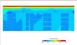
While construction was continuing, Simpson provided Flomerics consultant Chris Wark with 2D drawings of the building, rack configuration and HVAC layout. Wark began by constructing a 3D model representing the building and adding boxes to represent the product pallets. The most important specification needed was to model the air distribution system. This included the supply air volume, velocity and temperature as well as the physical locations of the supply diffusers and return registers. The ambient air temperature outside the plant and insulating properties of the building were also entered. Wark ran a steady-state solution on the computer. He showed Simpson the results by looking at temperature mapped as color contour charts across horizontal sections at various levels above the floor.
Figure 1: Temperature plane through middle of product pallets with initial design shows temperatures ranging from 69°F to 74°F at 20 4 level with 95°F outside temperature
Next Simpson asked Wark to utilize the full power of a CFD model by modifying it to account for several alternatives that he was considering to reduce the temperature stratification in the building. The first option was to install eight 24-inch diameter Greenheck model MCY-24 fans and the second option was to install 50 smaller Airius destratification fans. The Greenheck fans, because of their large size, require fewer fans for enhanced destratification over pallets but also generate more noise and higher air velocities. The Airius fans are smaller, quieter, more difficult to see as they are the same color as the ceiling, more energy-efficient, easy to install and generate a lower air velocity but require the installation of many more fans. The purpose of simulation was to determine, in advance, exactly what results would be provided by each type of fan.
Evaluating Design Alternatives
Wark created two new modified versions of the model. Flovent software would have been capable of modeling the actual geometry of the fans and this would have been required if their performance was not known. However, the manufacturers of each of the fans provided detailed performance specifications including fan curves that provided airflow as a function of pressure. Wark used SmartParts software, that is provided with Flovent, to simulate fan performance to a high degree of accuracy while using far fewer computational resources. He selected SmartParts that were similar to the fans he needed to model and modified their parameters to match the specifics of the two fans under consideration.
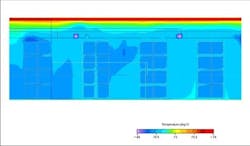
Wark re-ran the simulation for each of the new models and he and Simpson viewed contour maps that showed temperature at key levels of the warehouse. The results showed that each type of fan reduced the temperature stratification within the building to +/- 1°F. Wark also provided additional simulation results that showed air velocities within the building. The results indicated that the larger Greenheck fans generated air velocities at a level that would cause the users paperwork to be blown about, making it difficult for warehouse personal to do their jobs. On the other hand, the smaller Airius fans provided much lower air velocities that would not interfere with people working in the warehouse.
Figure 2: Vertical plane through middle of product pallets with 50 Airius fans added shows reduction in temperature stratification
Simulation Helps Meets Customer Requirements
Simpson and Wark showed these results to the client and they agreed to purchase the Airius fans despite the fact that they represented a higher cost solution. The simulation results were crucial not only in determining what equipment would work best but also in providing graphical evidence that this equipment was needed to provide a tighter temperature control, Simpson said. In particular, we had never used the Airius fans and were leery of purchasing them and installing them based solely on performance specifications provided by the vendor. Without these results, we would never have been able to prove to the client that the fans worked or not.
Next, Eichleay had the 50 Airius fans installed in the building. Validation of the warehouse space was accomplished by monitoring 54 temperature sensors evenly distributed throughout the space at three different levels. The validation protocol first tested the system without the destratification fans and then again with the destratification fans. The first validation test passed within the +/- 3.5°F criteria. The second validation test passed within +/- 1°F as predicted by both of the Flovent program runs.
The new HVAC system has been up and running for about 18 months and since then, the temperature alarms have not shown any excursions, Simpson said. Most importantly, the customer is extremely pleased that the building has met their requirements.
For more information, email [email protected], or visit http://www.flovent.com.


