Life Science Level Measurement: An Update
Accurate level measurement is critical in drug manufacturing, to ensure that final product is within the required tolerances, but traditionally it has not been easy. Challenges that manufacturers face regarding level measurement include the reliability of the system under changing process conditions, calibration verification required by ISO/FDA standards, conformance to bioprocess standards, and the need for redundant level measurements to prevent catastrophes, such as spillage.
This article will look at how pharma and biopharma manufacturers are addressing these issues head on, and at how modern technologies are making level measurement simpler and easier.
Using GWR for Changing Conditions
Fermenters, bioreactors, mixers, and prep tanks have built-in agitators and nozzles which make it difficult to use certain types of mechanical level technology, such as magnetostrictive. Some level sensors, such as hydrostatic pressure, are not able to consistently provide an accurate measurement as the process in the tanks undergoes changes in pressure, temperature and density. The presence of foam increases the challenge of reliable measurements.
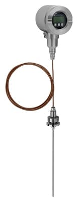
Many manufacturers have turned to guided wave radar, and various products are on the market for life science applications (Figure 1). GWR sensors use a stainless steel probe that extends into the tank. A low energy microwave pulse is launched down the probe and into the vessel. When the pulse contacts the liquid surface it responds to the change in dielectric between the vapor and the liquid. The change in dielectric creates a change of impedance that reflects the pulse back from the liquid surface to the transmitter. Newer guided wave radar devices will read to almost all the way to the tank bottom.
In most cases, the vessels use clean-in-place or sterilize-in-place processes, and any level sensor must be able to endure the pressures and temperature of CIP or SIP. When designed for the life sciences industry, guided wave radar will also be unaffected by the spray ball operation that is part of many CIP and SIP procedures as well.
Furthermore, clean up of the outside of the vessel and the room itself is often done using high pressure washdown hoses and nozzles. It is important that a level transmitter meets an ingress protection rating of IP69K, which certifies that the level transmitter housing, cable glands and seals will remain watertight even in the presence of water jet sprays above 1400 psi.
In other processes, the probe must go through an autoclave before each batch. A level transmitter with a removable head allows the probe or sensor to be detached and capped. The probe can be autoclaved without exposing the electronics to the temperatures required by the autoclave process.
A guided wave radar level sensor is unaffected by typical changes in process parameters. It will continue to provide accurate and reliable level indication even with significant changes in pressure, temperature and density or the presence of foam. Other types of level sensors that may also work under such conditions include free space radar and ultrasonic or hydrostatic pressure.
Meeting Standards
Any level probe must meet life science standards, such as FDA 21 CFR Part 177.2600 for hygienic applications, as well as Biocompatibility USP Class VI. This typically requires wetted parts of stainless steel 316L 1.4435 with a surface finish that has been electro-polished to the application requirements. The sealing materials must be FDA and USP 88 Class VI and USP 87 compliant.
Other standards include ASME BPE (2009) material certifications for bioprocess equipment. The equipment may require 3-A sanitary standard and European Hygienic Engineering & Design Group (EHEDG) approvals, depending on the application.
In addition, there needs to be a document package for each instrument that includes certificates of the listed independent organizations, and a certificate of compliance (COC) for all wetted parts, such as the sensor or rod. Additional certifications for the passivation or the surface finish to ASME standards are not unusual.
Calibration Verification
To maintain batch integrity in the life sciences industry, it may be important to regularly validate the calibration of the level measuring transmitters. Typically, this is done with a wet calibration procedure, where water or some other liquid is pumped into the vessel to a known volume, and the level readings are compared to known references. Unfortunately, this requires taking the vessel out of service for the calibration procedure.
A newer technique, Calibration Verification, provides an in situ verification. The user does not need to remove the probe from the process to verify the unit is still functioning within published specifications. This ensures the user is still obtaining accurate and reliable level indication without needing to break sterility on the vessel or even taking it out of service.
A calibration verification kit is available for some guided wave radar level transmitters. The calibration verification kit comes with cable probes of various lengths. After the unit is initially commissioned, the transmitter is removed from the probe and the probe can remain in the tank, thus not interrupting the sterility of the vessel (Figure 2). The transmitter is connected to one of the calibration cables. The length of the calibration cable can be read off the transmitter display and the value annotated. This step is then repeated using a different calibration cable, or multiple calibration cables can be connected in series to give a longer distance reading.
All subsequent calibration verification data will be compared to the reference measurements to ensure the electronics are operating within published accuracy specifications. The calibration verification procedure can be accomplished in a few minutes, without breaking sterility.
Establishing Redundancy: Tuning Fork Sensors
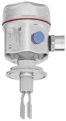
It is good engineering practice to have redundant level sensors—such as point level switches (Figure 3)—which can be used to ensure overspill protection. Most processes in biopharmaceutical manufacturing have high-level limits for pumpable liquids.
Point level switches act as a backup in case the main level sensor fails. They can indicate a high or low level regardless of buildup, density changes, pressure changes, and so on. Their main purpose is to prevent overspills, but they can also be used to verify discrete levels in certain steps of a batch process.
Earlier point level devices—mechanical, float type, capacitance and gap switch sensors—had issues with failures from the challenging process conditions as described above. A newer technology, using a tuning fork sensor, eliminates those problems. A tuning fork sensor has dual forks that vibrate at a resonant frequency. When liquid covers the sensor, it causes a shift in frequency, which is detected by the electronics, which switches a contact. The sensor is independent of temperature, pressure, density and viscosity changes.
A tuning fork sensor does not require any calibration, has no mechanically moving parts, requires no maintenance, and offers a long operating life. However, like most sensors, a tuning fork can become corroded or coated with material, which adversely affects its operation and can result in failure of the sensor.
Modern tuning fork sensors have built-in diagnostics that detect any change in the frequency oscillation that indicates corrosion or buildup, and sound an alarm when the sensor performance degrades to the point where maintenance or replacement is required.
About the Authors
Ravi Shankar is Industry Manager—Life Sciences, and Al Dhanji is Level Product Business Manager, for Endress + Hauser USA. They can be contacted at [email protected] and [email protected].


