The correct selection of depth filters can significantly improve the productivity of any cell culture purification process. However, if the filtration is not optimized early on, problems such as low product recovery, premature plugging, an excess of DNA and Host Cell Protein (HCP), and lack of scalability can occur, resulting in major problems downstream. Optimizing depth-filter performance requires a clear understanding of the specific fluid characteristics and batch-to-batch variability. This article will summarize basic requirements for optimizing selection.
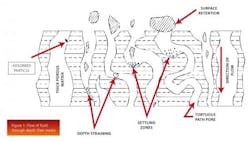
Depth filters remove particles, submicron particles, colloidal material, and soluble material by taking advantage of the depth of a particular media (think of a sponge) to enable high levels of contaminant removal. The fluid must travel through a tortuous path before it is able to reach the other side. Figure 1 illustrates the flow of fluid through depth-filter media.
It is logical to assume that contaminants that are larger than the filter pore size would easily be removed by mechanical filtration. This mechanism is also referred to as sieving, straining, or size exclusion.
However, the removal of contaminants such as DNA and HCP is less intuitive. Another purification mechanism that operates with depth filters is adsorption, attracting the contaminants using either electrokinetic or surface affinity. Figure 1 also illustrates an adsorbed particle within a depth filter.
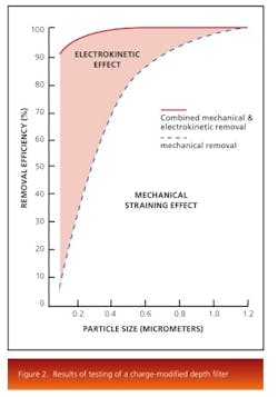
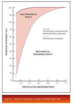
The electrokinetic effect present in charge-modified depth-filter media makes removal of these submicron particles, colloidal material, and soluble contaminants possible. Depth media are designed and manufactured with various pore structures and surface modifications. Figure 2 shows the results of testing of a charge modified depth media under the same conditions as a non-charged modified media.The results show that both filters perform equally at the mechanical removal of large particles, while the charge modified filter is more efficient at removal of submicron particles through adsorption. Pore surface chemistry also plays an important role for the removal of contaminants. The removal mechanism works by selecting a filter that has a pore surface energy lower than that of the contaminants. Thereby, the contaminants, driven to reduce their surface energy, would be attached to the pore surface of the depth filter and removed from the liquid stream.
To select the optimum depth filter, it is necessary to research commercially available filter media. There is a wide range of depth-filter media available including but not limited to:
- positively charge modified for removal of negatively charges species
- carbon impregnated for specific adsorptive properties
- high silica for lipid removal
- low pyrogenic for pyrogen-sensitive applications
Depth filters are nominally rated, since there is no one standard contaminant that can be used to challenge all filters and address the complexity of cell culture media compositions. Therefore, it is necessary to test several filters for each application.
In filter optimization, the main goal is to maximize filter capacity. In this regard, dual layer products take advantage of gradient pore size structure within a filter. The larger pore-size filter is placed upstream of the finer pore-size filter. Larger contaminants are captured within the upstream layer while smaller particles are removed by the downstream layer. As a result, a larger distribution of contaminants can be removed in a single step.
The first step in designing a filtration train is determining what needs to be removed or reduced and what should not be removed. Small-scale testing for each process and/or product is important. In many cases for mammalian cell culture, a few pore sizes of charged depth media in various configurations would be tested. In order to measure the effectiveness of the filter, data such as total cell density, viability, turbidity, and titer would be recorded just prior to filtration. During optimization, the differential pressure across each filter, the weight/volume of filtrate, and turbidity of the effluent is monitored until a terminal differential pressure is reached. The turbidity, titer, DNA concentration, and HCP concentration of the pooled filtrate would be recorded and product quality analyzed to determine the optimal filtration scheme.
Reviewing total cell density, viability, and turbidity is a quick way to review batch-to-batch variation. Titer data pre- and post-filtration will show if any product is being retained in the filter. Turbidity of each pool is an indicator of filtrate quality and depth-filter effectiveness, and should be compared qualitatively, especially when a sterilizing membrane filter is used downstream.
If the desired effluent quality is obtained, the next step will be to size the filtration train for a given scale. By analyzing the pressure drop and weight/volume data, throughput is calculated and is used for sizing a system.
Throughput is represented as a normalized value with units of volume per unit area, commonly recorded in liters per meter squared (L/m2). The value for filter throughput capacity is used to determine amount of filter area needed for any given size filtration.
For example, say that one liter is to be filtered with a 25 centimeter squared (cm2) filter. When the experiment is completed, it could be recorded that 0.85 liters (L) was filtered when the terminal pressure drop was reached.
This data could then be used to determine the filtration surface required for a 150-liter batch by dividing 0.85 L by 25 cm2 filter area to get 0.034 L/cm2 or 340 L/m2. Next, divide the desired batch size of 150 L by the 340 L/m2 capacity to obtain 0.44 m2 of required filter area.
Filter throughput capacity depends upon the particular flow rate and grade/pore size of the depth filter that was tested. If the recorded flow rate during the small scale test was 7 ml/min, flow rate can be calculated for the 150 L batch. This is done by dividing the flow rate of 7 ml/min by the filter area of 25 cm2 obtaining 0.28 ml/cm2/min or 168 LMH, a commonly used “liters per meter squared per hour” unit. This value is used to determine the flow rate for any size filtration by multiplying filter area 0.44 m2 and 168 LMH (74.1 L/hr = 1.2 L/min). Note that the exact 0.44 m2 of required area could not always be available. The calculation should be repeated with the available filter surface area. Depth filters are designed in modules and next size up is usually recommended.
This leads to some excess of filter area, or safety factor, which accommodates potential process and batch-to-batch variation.
Although every product and process is unique, generally the following statements will hold true:
- Lower flow rates per unit filter area lead to higher filter capacity (L/m2).
- Smaller pore size and higher charged media are more effective in removing DNA and HCP.
- Cell morphology, total cell density, and viability of a harvest impact filter capacity.
- If using a positively charged depth-filter media, the product’s isoelectric point (pI) should be greater than the pH to achieve the highest product recovery.
- Factors such as hold-up volume, scalability, ergonomics, and ease of use can vary by specific supplier and should also be considered when determining a filtration process.
There are many factors to consider when developing a filtration process for a product — titer, turbidity, DNA/HCP, and filter capacity. By executing small and mid-scale tests and understanding more about depth-filtration performance, a robust process can be developed which can provide consistent product quality, reliable results for scale-up, and shortening the process cycle time.
Sometimes mistakes arise during scale-up phase, which have relatively simple solutions. Here are some examples:
Case 1. The first test performed showed a 98% product yield, and now it is closer to 90%. The filter media was exactly the same, the flow rate was the same, and the product/process was the same. How could the difference be explained?
Potential solution: There could be a number of different root causes, however, it likely had to do with the pre and/or post flush of the filter. Essentially, the product might not have been lost, but diluted with buffers which were used for the flush(es). A mass balance experiment can be done to verify if this is the case.
Case 2. In a two-stage filtration, it seems that terminal pressure drop is being reached earlier than expected.
Potential solution: A pressure gauge upstream of both filters will read the system pressure drop, the pressure gauge upstream of the second filter will read the second filter’s pressure drop, and the pressure drop of the first filter will have to be calculated by subtracting the second filter pressure drop from the system pressure drop. It is likely that the system pressure drop is being recorded instead of the first filter’s pressure drop. Note that each supplier has different specifications for maximum system pressure drop and individual filter pressure drop.
Case 3. In calculating the amount of pre-rinse needed for the filter, the value was 100 times the amount specified by the supplier.
Potential solution: It is likely that there was an error in unit conversion. Although there are 100 cm per meter, there are 10,000 cm2 per m2. It is critical to review calculations and unit conversions in order to ensure the accuracy of results.
About the author
Brittany Nixon is currently a Scientific Applications Support Service Specialist (SASS) at 3M Purification in the Life Sciences Process Technology Group. She assists many biotech companies in filter selection and optimization. She may be reached at [email protected].
Reference
Hou, K., et al. Capture of Latex Beads, Bacteria, Endotoxin, and Viruses by Charge Modified Filters; Applied and Environmental Microbiology, Nov. 1980.


