Tales from the Front: Applying Fieldbus at Genzyme, Part 1
Editor’s Note: It has been said that most pharmaceutical companies fail to capture and use more than 10% of the information coming from the instruments already installed in their manufacturing plants. This information could facilitate equipment troubleshooting and trending and improve overall process control, alerting operators to upcoming equipment failures before multi-million-dollar batches are destroyed. In the past, a major drawback has been the cabling required for controlling instrumentation at the field level.
Now, some manufacturers are turning to fieldbus communications systems to connect sensors, actuators and control elements so that process control can be distributed across a Local Area Network, and processes controlled at the field level.
Fieldbus standards took decades to take shape, and “warring” protocols are out there, including Foundation fieldbus, Profibus, AS-interface (AS-i) and DeviceNet, each with its own unique strengths. Rather than choose one or another, Genzyme used four different fieldbus protocols in a multi-fieldbus control system at one of its biopharma facilities in Massachusetts, reducing cabling requirements and improving maintenance. Taking advantage of new equipment diagnostics, the installation is expected to eliminate waste that might otherwise result from undetected maintenance needs and equipment failure. Such waste would be even less tolerable at this Genzyme facility, given that the products at stake are orphan drugs, critical therapies with small markets, and the only treatments available for some rare diseases.
This two-part article, adapted from an article previously published in our sister publication, Control magazine, examines how Genzyme went about choosing and implementing fieldbus protocols and technology, and adapting them to the unique needs of a biopharma manufacturing plant. Could fieldbus be right for your facility? See the checklist below (Is Fieldbus Right for You?) to find out.
GENZYME CORP. RECENTLY INSTALLED a multiple-fieldbus control system platform at its 12-year-old pharmaceutical manufacturing facility in Allston, Mass. (see Optimizing Manufacture of Orphan Drugs, below) The new control system is used exclusively in a manufacturing suite that produces Myozyme, a drug that is used to treat Pompe’s disease, often fatal in young children. The condition is caused by a defective gene for the acid maltase enzyme, which affects the storage of glycogen in the body.
Fieldbus is used in process areas, electrically rated as “general purpose” and “Class 1, Division 2.” Process areas included in the multi-bus control system include mammalian cell culture, purification, clean-in-place (CIP) and steam-in-place (SIP). Bus technology has been deployed on skid equipment, which includes bioreactor skids, chromatography skids, ultra-filtration skids and CIP skids. Bus technology has also been stationed on stick-built fixed vessels, associated piping and transfer panels. Fieldbus protocols included in the facility are Foundation fieldbus, Profibus-DP, AS-interface (AS-i), and DeviceNet.
Baptism by Fire?
This project was our introduction to bus technology at Genzyme. We selected fieldbus technologies based on process equipment needs in a cell culture and protein purification manufacturing environment.
We knew that fieldbus instrumentation would be more expensive to install than the alternatives, but we felt that it could reduce controller cabinet size, cable count and conduit sizes and quantity. However, we believe that our biggest savings are still yet to come with the predictive maintenance model inherent in the Foundation fieldbus protocol. Foundation fieldbus transmits device status along with the process variable, allowing one to receive information on device health and warnings of impending failures. In biopharma, this can mean the difference between a successful multi-day or month batch run and a failure resulting in millions of dollars worth of lost product.
This two-part article (part two will run in October’s issue) will summarize our experiences installing fieldbus control at this facility, and discuss the implications of fieldbus technology for facility constructability, software design, commissioning, metrology and calibration, validation and maintenance.
Which Fieldbus Where?
We selected DeltaV from Emerson Process Management as the host controller, primarily for its batch capabilities. DeltaV is fieldbus-ready for the following fieldbuses: Foundation fieldbus, Profibus-DP, AS-i and DeviceNet. The project’s total I/O count was approximately 4,000 points.
When we began the project in 2003, it was relatively easy to find fieldbus-enabled pressure, temperature, flow, pH, conductivity, level and modulating control valve applications.
At the time, though, we could not find fieldbus-enabled versions of some of the instruments critical to biopharma manufacturing processes: dissolved oxygen instrumentation, for example, used for in situ measurement in bioreactors, or vessel weight indicators (strain gauge type). In addition, UV analyzers for liquid chromatography weren’t available in fieldbus versions. In addition, mass-flow controllers, used extensively with bioreactor equipment, weren’t Foundation fieldbus ready, but were available with a Profibus-DP interface.
We overcame these obstacles by using 4-20 mA current-to-fieldbus converters for dissolved oxygen, vessel weight and UV analyzers, and using a Profibus interface for the mass-flow controllers.
ASi Eases Valve Control...in General Purpose Areas
Valve control for open/close valves and the discrete input devices used in the general purpose electrical environment could be easily addressed with the simple AS-i bit-bus. There were many opportunities for actuating rising-stem or quarter-turn valves, which are used primarily for sanitary diaphragm valves and quarter-turn ball valves. AS-i was also used for discrete input devices, such as valve limit switches and proximity switches found on process transfer panels.
AS-i may have simplified installation, but at the time, it had limits: three years ago, one could not exceed its segment length criteria of 100 meters, so, after every 100 meters a repeater and a power supply had to be added. This is no longer the case. Now, this bus can extend for 300 meters without repeaters, instead using a bus tuner that sits at the end of the segment.
We didn’t perceive length limit as a problem, though, because most of the valves are clustered in close proximity to one another, especially on skid equipment, so we embraced this bus for most of the discrete I/O requirements.
However, the AS-i bus isn’t suitable for use in electrically classified process spaces, due to its high power requirements. For this reason, we opted for Profibus-DP to handle open/close valving and discrete input devices in electrically classified environments with intrinsically safe remote I/O.
Profibus or DeviceNet Required for Motors
Either Profibus-DP or DeviceNet could address single-speed and variablespeed motors, many of which are used in biopharmaceutical manufacturing. We chose DeviceNet mainly because the host system features a rather nice graphical interface that allowed configuration of any node device at the host location.
We needed to configure drives for full-load amps for overload protection, acceleration and deceleration ramp rates, stop modes of coast or ramp, etc. The host DeviceNet interface also gave us the ability to troubleshoot drive issues.
The following example shows how Genzyme’s multi-bus architecture was deployed in one of our process suites.
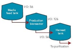
Figure 1 (right) shows a typical bioreactor train, which comprises a media feed tank, bioreactor, and harvest tank with their I/O requirements. If this bioreactor train had been conventionally wired, a combined total of 238 cables would have been pulled between a controller cabinet and the process equipment.
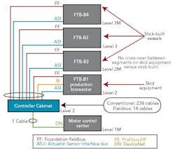
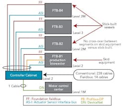
Figure 2 (below) depicts a cable block diagram for a fieldbus implementation of this same bioreactor train. You’ll notice that there’s a dramatic reduction in the cable quantity; only 14 homerun cables are required between the controller cabinet and the field terminal boxes (FTBs). These FTBs are strategically located in the process suite close to the process vessels to minimize instrument cabling that fans out from the FTB to each instrument.
FTB-B1, which wires to the bioreactor skid, includes two Foundation fieldbus segments, two AS-i segments, and one Profibus segment. The segments don’t extend beyond the bioreactor to other vessels, even if they have instruments near these segments. This approach was taken to maintain segment segregation between skid equipment, such as bioreactors and field-assembled, fixed tanks.
Bioreactors are the only process skids that use redundant instrumentation, specifically, dissolved oxygen and pH measurement. These redundant instruments share the same segment. We didn’t design for redundant segments in this case, because a bioreactor is unique in that all instruments and valves must be functional or the reactor will be shut down. The redundant transmitters provide assurance that at least one will remain operational by the end of a bioreactor run, even if there’s a sensor failure or probe fouling on one of the two. Sensors can’t be changed under way because they’re within the sterile boundary of the reactor.
FTB-B2, 3 and 4 are distributed by elevation, to pick up the top and bottom instruments of the media and harvest tanks for our bioreactor train. Foundation fieldbus and AS-i bus are both powered buses, and no additional power supplies are required in the FTBs. One DeviceNet segment exists to pick up the agitators’ variable-speed drives and single-speed pump motors.
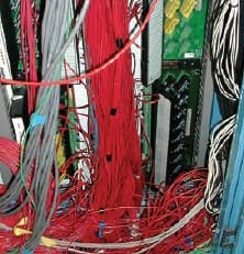
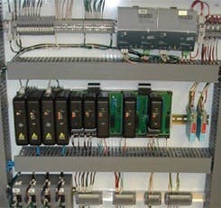
The fieldbus architecture allows controller cabinets to be maintained in an orderly way. Figures 3 and 4 (above) offer a “before” and “after” perspective. The fieldbus-enabled cabinet uses five bus I/O cards that communicate with approximately 200 I/O points.
Fieldbus Segment Design
The buses selected for our facility fall into two distinct categories — powered buses, including Foundation fieldbus and AS-i bus, and unpowered buses (Profibus-DP and DeviceNet). The powered bus includes the communications and device power on the same wires. The overall topology used for the powered bus is known as chicken foot (Figure 5, below).
One design element that we thought was important to carry over from the conventional world is short-circuit protection for each device. Because one trunk provides power and communication to all devices, we couldn’t afford to have one device take down an entire segment if it encountered a short.
Moreover, it would be difficult to identify the offending device without disconnecting devices one by one until the shorted device or cable was found. Short-circuit protection is normally provided for the segment trunk with the segment power supply.
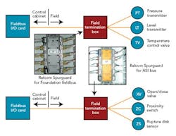
The FTBs would house this shortcircuit protection equipment for field devices of both powered buses, and we hoped to identify a common short-circuit device type that could be used for both Foundation fieldbus and AS-i. At the time of our detail design effort, Relcom offered its Spurguard for Foundation fieldbus. We’d also hoped to find something in a similar form factor for AS-i.
At our request, Relcom designed and manufactured a Spurguard for AS-i, which enabled all our powered buses to have the same look and feel. Figure 6 (above) illustrates where these Relcom Spurguard devices are located.
Our project’s ultimate goal was to have the stick-built process equipment, which included vessels, transfer panels and skid equipment using an identical segment design approach. This allowed us to develop segment design standards that were followed by our engineering design contractor for the stick-built process equipment and by the various skid vendors.
About the Author
William T. Dolan, P.E., is principal instrumentation and controls engineer at Genzyme Corp. in Allston, Mass. He can be reached at [email protected]
