S88 Redefines Clean in Place Operations
June 8, 2005
13 min read
When ISAs SP88 committee began development of the now familiar ANSI/ISA-S88 (Parts 1-3) Batch Control standard (S88), few people outside the software engineering environment knew much about object-oriented and class-based programming techniques.SP88 committee members understood that there was a great need for improving how batch processes were defined. They also knew that batch processes, regardless of company, industry or locale, contained similar unit operations with similar equipment, such as fermenters, batch reactors, holding tanks, filtration systems, and Clean-in-Place (CIP) skids and valves.Today, S88 is an internationally recognized standard that emphasizes good automation practices, is suitable for a broad variety of batch processes, is effective for any degree of automation being applied, and fits nicely into the class-based programming environment.An iterative design processOne of the things that makes S88 universally appealing for batch processes is that it promotes a structure of identifying and reusing identical and/or similar physical entities. S88 models define a hierarchy of physical entities and associated procedural elements (Figure 1, below). In S88 terms, these become the physical model and the procedural model.Figure 1. ANSI / ISA S88 as a modular design tool Work top-down when defining physical entities. Work bottom-up when defining procedural actions.
When defining batch processes, it is best to apply a top-down/bottom-up design approach. Begin at the top of the physical model and work downward, defining boundaries (process cells, units, etc.) and the specific equipment within each boundary (vessels, pumps, headers, valves, etc.). Once physical entities are identified, work upward from the bottom of the procedural model to define the actions that each piece of equipment and unit will perform.This model supports an iterative design process that helps identify reusable objects. The benefit becomes apparent when a process is undergoing initial designs, perhaps for budgeting purposes. Usually at this point, Piping and Instrumentation Diagrams (P&IDs) are not available and preliminary designs are based on Process Flow Diagrams (PFDs). Because equipment specifics are still undefined, automation designs are developed at a high level.Later, when P&IDs become available, the S88 model and its support for top-down/bottom-up designing makes expanding the details of the preliminary design easier. Additionally, the iterative design approach is well suited for achieving the true objective of object-oriented programming techniquesidentifying reusable software objects.The CIP process from concept to practiceFor many of us, a top-down/bottom-up iterative design approach, identifying class-based entities, and developing reusable objects, makes a lot of sense. But it is harder to understand what this approach looks like, and it is helpful to have a practical example.Clean-In-Place, or CIP, is a process frequently used in pharmaceutical and biotech manufacturing facilities to ensure that process lines, vessels and reactors are free of inorganic and organic contaminants. At the laboratory scale, equipment can be cleaned manually, but in large-scale production processes it is impractical to disassemble equipment and transfer lines to clean individual components. Instead, this must be done by sending cleaning solution through the process path, or CIP circuit, without disassembly. This introduces unique design challenges.Within flexible manufacturing facilities, other factors complicate CIP. Because process connections frequently change, it is necessary to identify, track and clean the multitude of possible product transfer paths from upstream to downstream vessels, and to supply CIP solution from a few shared CIP sources to a number of process units distributed throughout the facility.Even with preconfigured modules and efficiency tools, automating CIP activities and finding a solution that is easy to use, validate and maintain remains a challenge. Defining the boundaries and responsibilities of the various elements is a key step. There are several suggestions to keep in mind when defining boundaries:
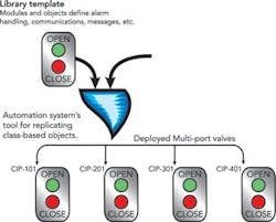
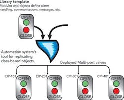
Figure 2. Class-based programming uses templates and inheritance Automation systems with robust, class-based probramming environments make use of standardized object templates and inheritance to develop, test, library and manage deployed objects. Users benefit because changes only need to be made in one place and inheritance handles updating the replicated objects.
- Seek identical or very similar entities
- Identify unique and one-of-a-kind entities
- Select several smaller objects, which provide more flexibility than a few large objects, and are easier to develop, validate and maintain.
When it is time to create the new instances, the engineering replication tool combines the software pieces from the objects library template with the device specific parameters described above in order to make all of the objects instances. For example, parameters for the instances are applied to the valve template to create the valve instances.Later, if a desirable feature, such as an interlock, needs to be added, inheritance permits making the addition to the library template and then replicating it to every instance using that unit object. Because of inheritance and automated replication tools, the field testing and validating of each object instance is significantly easier.A similar approach is used to create a CIP skid unit class template, and inheritance combines it with a variable list to develop instances of the CIP skids.From an object-oriented programming viewpoint, it is easy to understand how MP valves can be defined as a module class; each performs the same function. It is also easy to see how CIP skids can be grouped into their own unit class. Again, the equipment is nearly identical. Each executes similar phases (e.g., initialize, rinse, wash) while differences, such as those in concentration, temperature, time and flow rate for cleaning different process units, are handled by variables in the procedural model. Whats less clear is how object classes are able to accommodate more complex entities, such as CIP VMs.Defining the valve manifoldA common misconception about object-oriented programming is that it only works when objects are identical. While identical objects are the classic example, as long as the basic premise of an object remains the same, object-oriented programming concepts can be extended to accommodate non-identical objects, such as VMs.Robust class-based process automation systems that are based on the S88 physical and procedural models will include tools to help the user handle identical objects, such as the individual MP valves, as well as objects with nearly identical physical and/or procedural characteristics, such as VMs.Flexible production facilities are likely to contain complex product transfer paths resulting in complex CIP circuit requirements. VMs often have special considerations: there may be differences in the number of MP valves required, in how the many transfer paths are tracked for availability and operational status, and in the rules governing how and when concurrent paths are used may differ.To maximize the benefits available from object-oriented programming techniques, consider each and every difference in defining unit class boundaries. Depending on the degree of complexity, it may not be possible to create a single, all-inclusive, VM template. In such a case, it is still possible to create sub-modules that can be tested and assembled to form a VM library that supports customization while preserving most of the benefits of object-oriented programming.To create the best VM design:
Figure 3. Group similar physical entities that operate as one.
- Think beyond each VMs physical boundary
- Consider requirements one at a time
- Apply an iterative design process.
Resource management, failure handlingOnce CIP VMs are grouped, the next step is to revisit each CIP VM grouping to identify its usage limitations and establish the rules that will govern using the resources. This is sometimes referred to as resource management.Managing resources requires a means of enforcing the number of users (operators and/or automation procedures) that can acquire and use the resource at one time. Often resources are capable of supporting multiple, simultaneous users, but in the case of CIP VMs, limiting the number of users to one at a time for the upper header and one at a time for the lower header avoids contaminating a product transfer or interrupting CIP operations.
Defining who, when, and how resources are acquired and released during normal processing activities is fairly straightforward. Evaluating the events and conditions that justify the release of a resource during abnormal processing activities (failure handling) often receives less consideration but is extremely important.Ensuring that failure handling is adequately developed and resource management is appropriately addressed can produce huge dividends by avoiding unnecessary product contamination or loss.After determining resource management requirements, reexamine each VM, this time to identify and address equipment states (see box at right). Equipment entities, such as vessels and CIP VMs, have operational conditions that must be met before specific processing activities may begin or continue. For example, a fermenter must be clean before it can be inoculated, or a CIP VM that has been acquired and used to transfer a product must be cleaned before it can be released to another user.The tracking of equipment or transfer lines (e.g., dirty, clean, in-use) is known as equipment state-tracking and it must work in conjunction with resource management. After required equipment states are defined, rules must be established that identify the boundaries for equipment states. The rules help provide the consistency necessary to minimize the number and complexity of the software sub-modules.State-tracking rules appropriate for CIP VMs might include:
| SAMPLE EQUIPMENT STATES Dirty Default/initial state. Completion of CIP will automatically transfer the state to Clean. Clean Indicates CIP is complete. May start the clean timer. If the clean timer expires, the state changes to Clean Expired. Clean Expired Indicates clean timer is expired. CIP must be repeated to return the state to Clean. In-Use Indicates that a batch has started. If a Phase Hold occurs, the state transitions to In-Use Hold. Upon batch completion, the state transitions to Ready for Transfer. |
- Inlet headers (sources) are to be tracked by upstream (provider) equipment
- Destinations are to be tracked by downstream (receiver) equipment
- CIP VMs will track everything in between the source and destination.
About the Author
Christie Deitz and Dan Lorenzo
Senior Principal Engineers
Sign up for our eNewsletters
Get the latest news and updates
Sponsored Picks
Sponsored
Sponsored


