Laser Drilling Tablets for Use in Osmotic and Other Novel Drug Delivery Systems
The benefits of sophisticated drug delivery systems include decreased dosing frequency, more consistent drug concentration in the blood and even customized delivery profiles. In particular, osmotic drug delivery systems have proven valuable for providing controlled release of molecules with inherently low oral bioavailability due to solubility or permeability limitations. The typical osmotic delivery system for a poorly soluble molecule comprises a drug layer and a push layer, surrounded by a semi-permeable membrane. After ingestion, water enters through the semi-permeable membrane causing the push layer to expand. This forces the drug to be pumped out at a controlled rate through a small orifice in the drug layer side of the membrane.
The typical orifice size in osmotic pumps ranges from about 600 µm to 1 mm. The tolerances on hole diameter and shape are usually relatively loose, at least by the standards of other precision manufacturing tasks. A nominal 600 µm hole usually has a ±100 µm tolerance on diameter, and an allowable ellipticity of 1.0 to 1.5. Holes of these dimensions and tolerances could be produced by purely mechanical means; however, no mechanical method has proven capable of working at throughput rates that are consistent with other stages of the pharmaceutical manufacturing process.
In contrast, laser tablet drilling supports throughput rates of up to 100,000 tablets/hour, and can easily produce holes with the necessary dimensional tolerances and cosmetic appearance. As a result, laser drilling has become the technology of choice for this type of orifice production as well as other drug delivery systems whose operation is critically dependent on the presence of one or more small holes in the tablet coating.
System Operation
The main functional elements of a commercial, laser-based tablet drilling system are shown in Figure 1 (below). This particular configuration utilizes two laser drilling stations and can drill either one or both sides of a tablet.
Tablets are first introduced on to a single line conveyor from a bowl feeder. A color sensor views each tablet to determine which side is facing up. For osmotic pumps, tablets typically are colored brown on the push layer side with a pink or yellow drug layer side. The hole thus needs to be drilled only in the yellow (or pink) side.
Next, a presence sensor detects the passage of a tablet. The laser drilling process commences if the results from the color sensor were that the tablet was facing right side up. Tablets then pass through a machine vision inspection system. A digital image of each passing tablet is acquired and compared against the four possible outcomes, listed in the table. Two of these outcomes constitute a pass and two are considered a reject.
|
Pass |
Reject |
| Drilled and top side up | Drilled and bottom side up |
| Not drilled and bottom side up | Not drilled and top side up |
Rejected tablets are removed from the conveyor by an air-activated blow-off system. Because of the speed at which the conveyor moves and the physical response time of the blow-off system, the reject mode is activated as soon as a failed tablet is sensed by the vision system. This typically causes one or two tablets ahead of the rejected unit to be expelled as well. The reject state is usually left on until the system sees five tablets in a row that meet either of the two pass criteria. An additional presence sensor downstream from the blow off verifies that no tablets are passing through the system when the reject condition is set to on. Despite the fact that some good tablets are rejected by this rigorous approach, the system still typically operates at 98% efficiency (tablets in/tablets out).
After transiting the first laser drilling station, tablets pass single file through an inverter, and then continue on the conveyor through a second laser drilling station. This second laser drilling station operates in exactly the same way as the first. Its function is to drill any tablets that were wrong side up when they passed through the first drilling station. Alternately, to drill both sides of a tablet, the color sensors in both stations are set to trigger the drilling process regardless of tablet orientation. In that case, the vision inspection system is programmed to reject tablets only when no hole is detected. At the end of the line, processed tablets are fed into a collection drum, ready for final coating and printing.
Laser Requirements
Virtually any type of industrial laser can produce holes with the sizes and tolerances required for tablet drilling. Therefore, the primary selection criterion for the laser source is the throughput speed it can support. Secondary considerations are factors such as operating costs and uptime.
The maximum achievable throughput speed for tablet drilling is influenced by several laser characteristics. For example, if all other factors are equal, throughput increases when using a laser whose output wavelength is well absorbed by the material to be processed. High absorption in the processed material also ensures that no significant laser power penetrates through to other layers in the delivery system, where it might cause damage.
The organic materials used in drug delivery systems nearly all display strong absorption in the infrared, so a carbon dioxide (CO2) laser, with nominal output at a wavelength of 10.6 µm, is well matched for this task. In contrast, many organics are transparent at the near infrared output wavelength (1.06 µm) of industrial lasers based on Nd:YAG.
Most organics also are strongly absorptive in the deep ultraviolet, and therefore could be processed using excimer lasers. However, the material removal mechanism in the ultraviolet is substantially different than in the visible and infrared. Specifically, visible and infrared lasers remove material in a thermal process. In contrast, deep ultraviolet lasers directly break interatomic bonds, atomizing the material in a process called photoablation. Generally, heating removes material much faster than photoablation, making the former method better suited for high speed tablet drilling. Photoablation is more advantageous in high precision applications, in which either the amount of material to be removed is small or processing speed is a secondary concern.
There is a diverse range of commercially available CO2 lasers, offering output powers from a few watts to multi-kilowatts. Furthermore, some CO2 lasers operate in a continuous wave (CW) mode, while others are pulsed. A CW laser produces an uninterrupted beam of light, while a pulsed laser emits a stream of very short duration (<1 millisecond) bursts of light at high repetition rates (up to 100 kHz). Pulsed lasers exhibit very high peak power, which is the instantaneous power level at the most intense part of the output pulse, even if the total average power is relatively modest.
The high peak power of pulsed lasers enables processing of a wide range of materials, even including metals, with relatively low average power. This is advantageous because laser costs rise with increasing power. The short duration of a pulsed laser means that the material being processed is only heated for a very brief period. This allows for very precise process control and minimizes any heat induced effects, such as discoloration or debris formation. As a result, pulsed lasers are favored for processing applications where heat damage of surrounding or underlying material is a concern, or for structuring of high melting point materials. In contrast, CW lasers are typically used with materials, such as plastics or textiles, where bulk heating is not a concern, or for applications where it is actually desirable (e.g. heat treating and annealing).
On-the-Fly Drilling
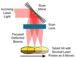
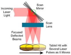
The second approach is to perform drilling using multiple pulses. In this case, it is necessary to optically track the motion of the tablet on the conveyor so that each pulse hits the exact same spot on the tablet surface. Typically, this is achieved with a galvanometer mounted mirror and a scan lens (see Figure 2, above right). The galvanometer scan mirror moves the beam in order to follow product motion. The scan lens is configured to maintain the proper beam focus even though the distance from the lens to the tablet changes slightly as product moves along the conveyor. The use of encoder feedback, together with a conveyor design that does not allow slippage of the tablet relative to belt, ensures that each pulse hits the tablet at precisely the same spot. This method also allows the process to produce multiple holes per tablet as well as other geometries, such as characters or graphics, although rates may be affected.
While the multiple pulse method increases the complexity of the laser beam delivery system, it enables a given processing task to be performed using about three to four times less laser power than in the single pulse case. This allows the use of a lower power, and therefore less costly, laser. The maximum number of pulses that can be used to process a single tablet depends on conveyor speed, the field of view of the scan lens and laser repetition rate. A typical tablet drilling process utilizes around nine laser pulses in order to drill a single hole.
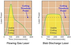
The exact pulsing characteristics of the laser have a significant impact on the economics and efficiency of the drilling process. For example, the graph in Figure 3 (above) compares the output power as a function of time for a typical flowing gas CO2 laser with that of a slab discharge CO2 laser. The output pulse from the flowing gas laser is roughly triangular in shape. In contrast, the short rise and fall times of the slab discharge laser lead to an essentially square wave shaped pulse. While, in the case illustrated, the peak power of the flowing gas laser is higher than that of the slab discharge laser, much less of this power is actually usable for cutting (the specific cutting threshold power is highly dependent on the particular material being processed).
The fact that each square wave pulse delivers more useful cutting energy means that it takes fewer of these pulses to perform a given processing task. Because of the interrelationship between maximum possible pulse count and throughput speed in on-the-fly drilling, this translates into a wider process window and greater flexibility. In addition, the reduction of waste energy serves to further minimize any heat induced damage in the processed material.
Some of these slab discharge CO2 lasers provide power on demand. This refers to the capacity to control the lasers pulsing characteristics, in real time, down to the single pulse level if necessary. In contrast, many industrial lasers operate with a fixed or narrowly variable pulse repetition rate. In many other laser types, individual pulses cannot be relied on to produce consistent results because the laser takes several pulses to reach its steady state performance level. However, the slab discharge design does not have this limitation and can be perfectly pulsed instantaneously. Therefore, power-on-demand allows the laser to be slaved to any arbitrary (and even variable) feed rate in a real production line. This is substantially simpler than attempting to adjust the mechanics of the conveyor system so that tablets are supplied at exactly the right time to synchronize with a fixed pulse-rate laser.
About the Authors
Graham Coffee received a BSME from the University of Alabama in Huntsville in 1981. He has worked for Control Micro Systems as the Chief Engineer for the last 16 years, and can be reached at [email protected]
Frank Gaebler holds a Dipl.-Ing. Manufacturing Technology degree from FhG, Institute of Lasertechnik, RWTH in Aachen, Germany. He has over 10 years experience in laser materials processing applications, and is currently Sr. Product Marketing Manager for CO2 lasers at Coherent. He can be reached via [email protected]


